Vision
Included in all Subscription licensesWork smarter,
not harder
Turn your material into outlined geometry for rapid nesting. Or trace your stone slabs with it's texture to get smooth pattern matching on your kitchen tops.
Simplified part placement
Anyone operating a CNC machine knows the time it takes setting up the material properly. Making sure your parts will fit the material and more importantly, making the machine start in the right position.
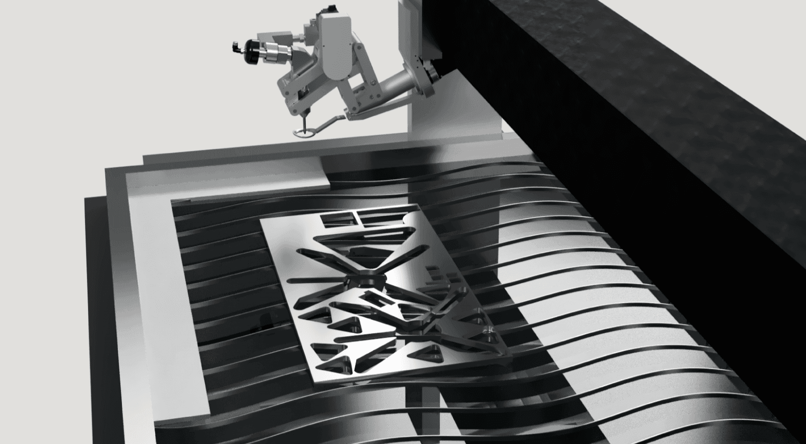 Photograph your material on the table from IGEMS CAD/CAM.
How does Snapshot work?
As illustrated above, a remnant sheet is placed on the table somewhere in the calibrated area. It's then photographed with the GigE camera and imported to IGEMS CAD/CAM by clicking the Snapshot command. When creating a sheet, select the image and it will create a traced sheet geometry from the image (it will try to detect what's sheet and what's not). Then you can use the Auto nest to utilize the whole sheet like the video above right.
Trace material from any camera
With the help of a photo station (four ArUco markers on a green background) and a camera, we can analyze and convert your material into geometry. A groundbreaking way of importing traced material into IGEMS CAD/CAM with the original texture.

The slab tracer works with any camrea, even your smartphone to import your image. Our smartphone app (IGEMS Waterjet) will sync directly with our servers and open in the Slab tracer command. Super smooth and super nice!
 Pattern match
Pattern match
Pattern matching opens up ways for you to match the veins of any stone or ceramic slab to your design. Be it a kitchen top or a compass rose in the floor, we have the tools for the job. Either match the pattern by click 'n drag or with the help of our famous Auto Nest.
Drag the elements below to pattern match the kitchen design (click to rotate).
Remnant sheets
It's sometimes difficult to know if a remnant sheet still got some life in it. The time it takes to find out often outweighs the amount of parts you can get out of it. With IGEMS Slab Tracer you can automatically generate the whole geometry of your material and import it into IGEMS CAD/CAM.
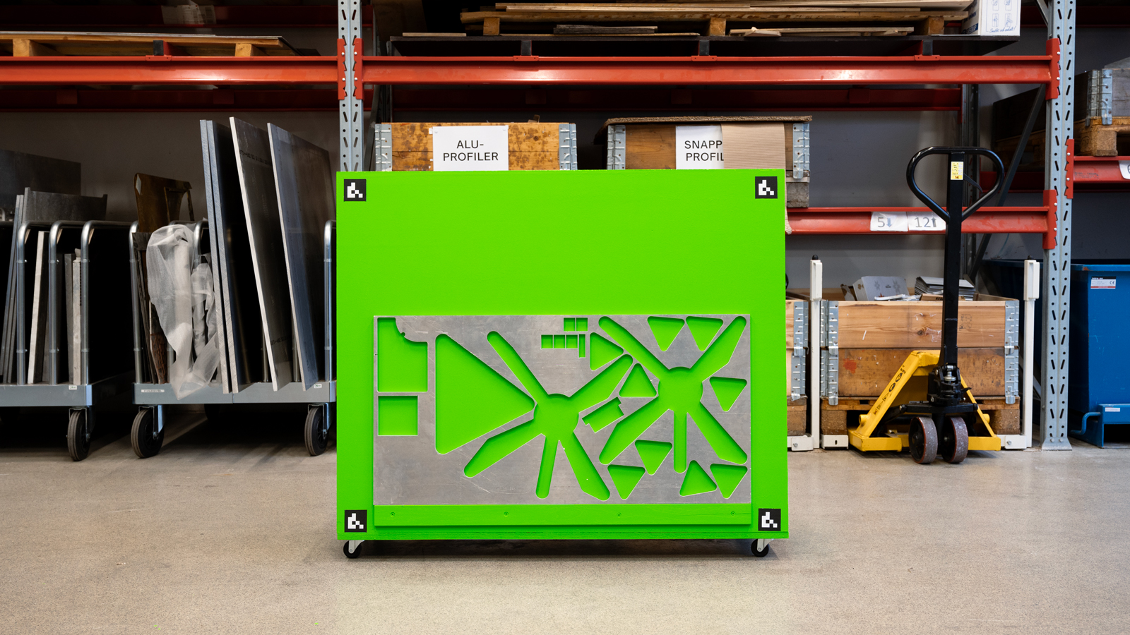 Trace remnant sheets in a photo station with any camera.
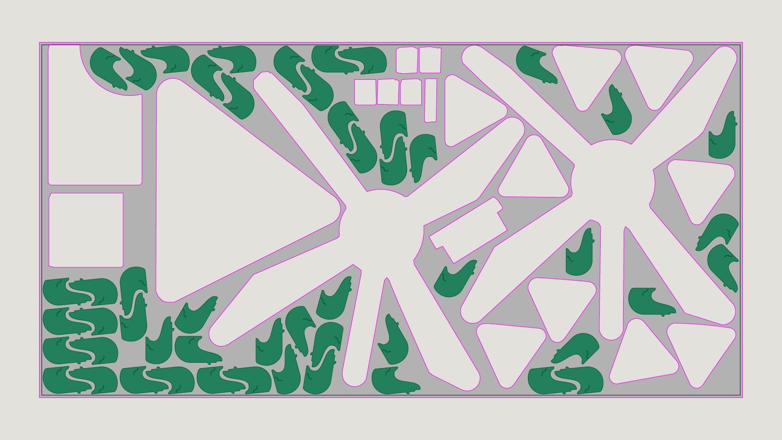 Use Auto Nest to fill the remnant sheet with parts.
By using IGEMS Auto Nest, you can easily nest parts onto the traced sheet within seconds. And there you have it. A fast and efficient way of getting more value from your remnant sheets.